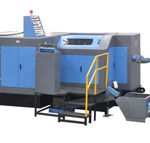
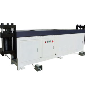
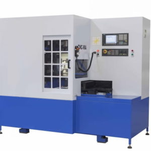
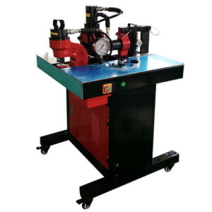
Description
CNC Busbar Punching and Shearing Machine Specifications
| MODEL | UNIT | AKS-PS200-5 | AKS-PS200-6 | AKS-PS200-8 | AKS-PS200-9 |
|---|---|---|---|---|---|
| MAX. PROCESS SIZE | MM | 6000*200*15 | 6000*200*16 | 6000*200*16 | 6000*200*16 |
| HOLE PROCESS SIZE | MM | Φ4-Φ34 | Φ4.3-Φ35 | Φ4.3-Φ35 | Φ4.3-Φ35 |
| MAX. MOULDS LOAD | P*S*K | 5*1*1 | 6*1*1 | 8*1 | 9*1 |
| KNURLING AREA PER PACE | MM | 160*60 | 160*60 | ||
| FORCE POWER | KN | 500 | 600 | 600 | 600 |
| MAIN MOTOR POWER | KW | 15 | 15 | 15 | 15 |
| MAX. PUNCHING FREQUENCY | TIME/MIN. | 60/100 | 120/150 | 120/150 | 120 |
| X AXIS MAX. STROKE | MM | 2000 | 2000 | 2000 | 2000 |
| X AXIS POSITIONING SPEED | M/MIN. | 48 | 75 | 75 | 65 |
| Y AXIS MAX. STROKE | MM | 530 | 960 | 960 | 700 |
| Y AXIS POSITIONING SPEED | M/MIN. | 35 | 35 | 35 | 30 |
| Z AXIS MAX. STROKE | MM | 350 | 310 | 310 | 600 |
| Z AXIS POSITIONING SPEED | M/MIN. | 35 | 35 | 35 | 20 |
| POSITIONING ACCURACY | MM/MM | 0.1MM/1000MM | 0.1MM/1000MM | 0.1MM/1000MM | 0.1MM/1000MM |
| HOLE PITCH ACCURACY | MM | ± 0.2 | ± 0.2 | ± 0.2 | ± 0.2 |
| DIMENSIONS | CM | 750*298*175 | 1100*280*178 | 1100*285*180 | 1100*290*180 |
| WEIGHT | TON | 55 | 61 | 62 | 63 |
CNC Busbar Punching and Shearing Machine Applications and Features
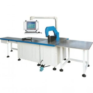
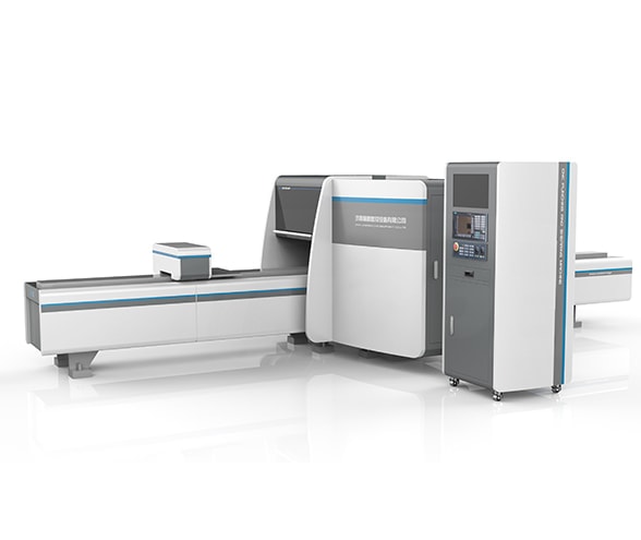
Application:Be used to produce Busbars in a variety of shapes, such as flat strips, solid bars, or rods, and are typically composed of copper, brass, or aluminium as solid or hollow tubes.Copper/aluminum busbar In electric power distribution, a busbar (also bus bar) is a metallic strip or bar, typically housed inside switchgear, panel boards, and busway enclosures for local high current power distribution. They are also used to connect high voltage equipment at electrical switchyards, and low voltage equipment in battery banks. They are generally uninsulated, and have sufficient stiffness to be supported in air by insulated pillars. These features allow sufficient cooling of the conductors, and the ability to tap in at various points without creating a new joint.
Features:
1.With functions of shape forming,hole punching,shearing,chamfering,slotting and knurling.etc.
2.3D programming software: The equipment supporting software is a special auxiliary design software developed by our company, which can be used on the network to realize programming automation. This software is the first to apply 3D graphics technology to the busbar processing industry. The advanced nature of this technology is international advanced. The software is convenient and quick to operate, and displays the processed shape of the copper busbar intuitively and three-dimensionally. It can accurately calculate the exact position of punching, shearing and folding of the workpiece, automatically generates machine codes, reduces the time for manual coding, and eliminates the possibility of errors in manual coding. The software can demonstrate the whole process of punching, cutting and folding to prevent material waste caused by manual code entry errors.
3.Main and auxiliary clamps: The maximum travel of the X axis is 2000mm at a time. The main and auxiliary clamps are used at the same time to reduce the quality requirements of the flatness and side camber of the busbar, and improve the machining accuracy. During the machining process, automatic Clamp the busbar, save labor, improve processing efficiency and processing accuracy.
4.Fast material pulling belt: After the processing is completed, the stainless steel material pulling belt is used to tow away the workpiece, which improves the efficiency and ensures that the machined parts have no wear.
5.Touch screen: human-machine interface, simple operation, real-time reflection of program running status, with display device operation alarm information function, can easily set mold parameters and operate equipment operation.
6.High-speed running system: The machine uses high-precision ball screws and linear guides to ensure that high-precision and high-efficiency. Components are well-known brands with long service life and guaranteed quality.
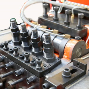
7.Mold tools library: It has multiple sets of mold stations (including shearing die, embossing die, and punching die), and the use of overall scissors can complete the cutting of the busbar at one time, which improves the processing accuracy, the verticality of the section and the processing efficiency; Dedicated embossing mold, large cross-section area, increase the contact area of the busbar, improve processing efficiency: simple mold removal and installation, safe and reliable, easy to change molds, providing a reliable guarantee for high production efficiency under frequent mold changes. The mold used can meet the requirements of accuracy and performance, and the number of mold impacts is ≤50,000 times.
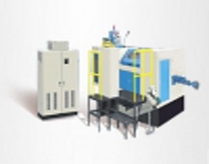
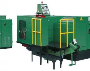
CNC Busbar Punching and Shearing Machine Structure and Components
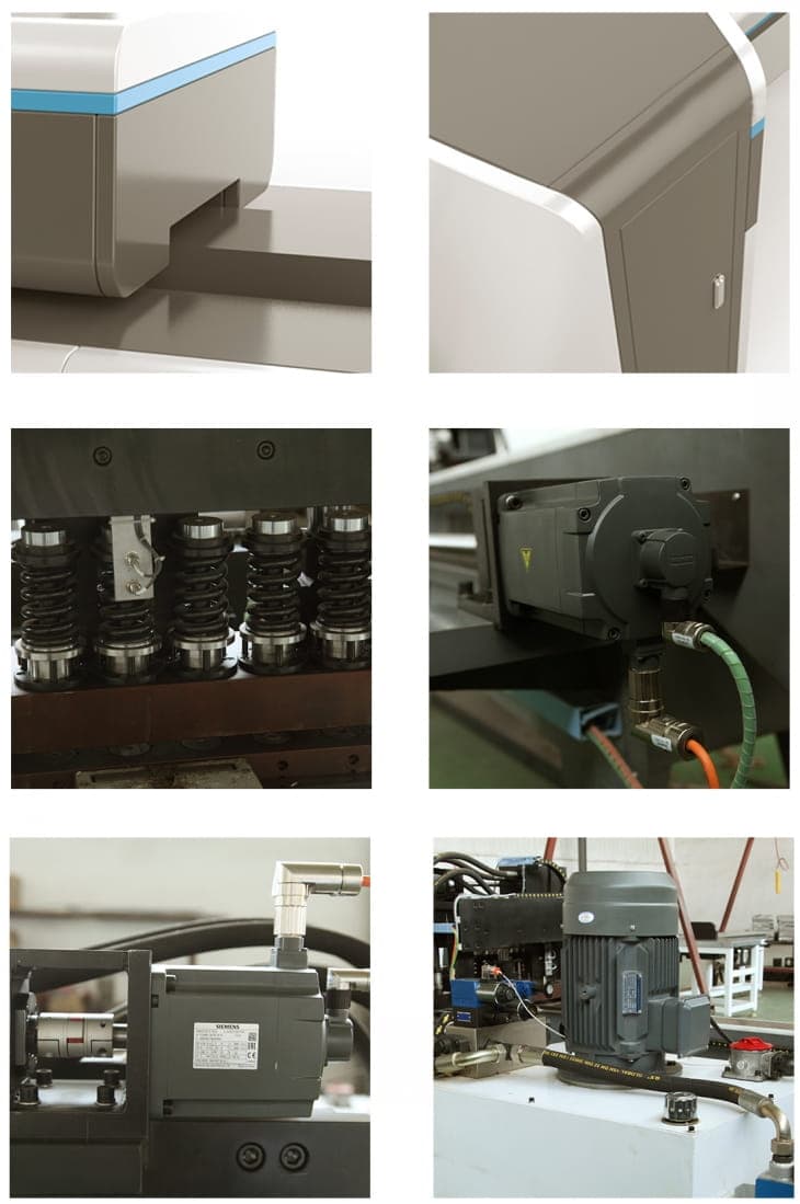
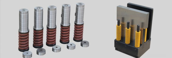
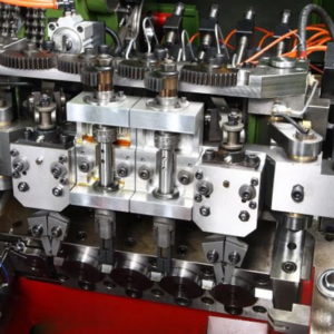
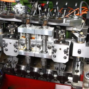
CNC Busbar Punching and Shearing Machine Hole Punch Die and Shearing Die
CNC Busbar Punching and Shearing Machine Produced Busbar Samples
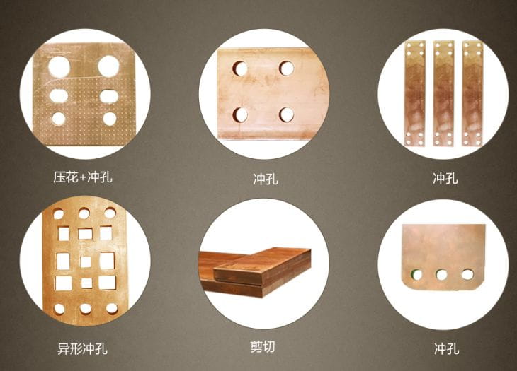
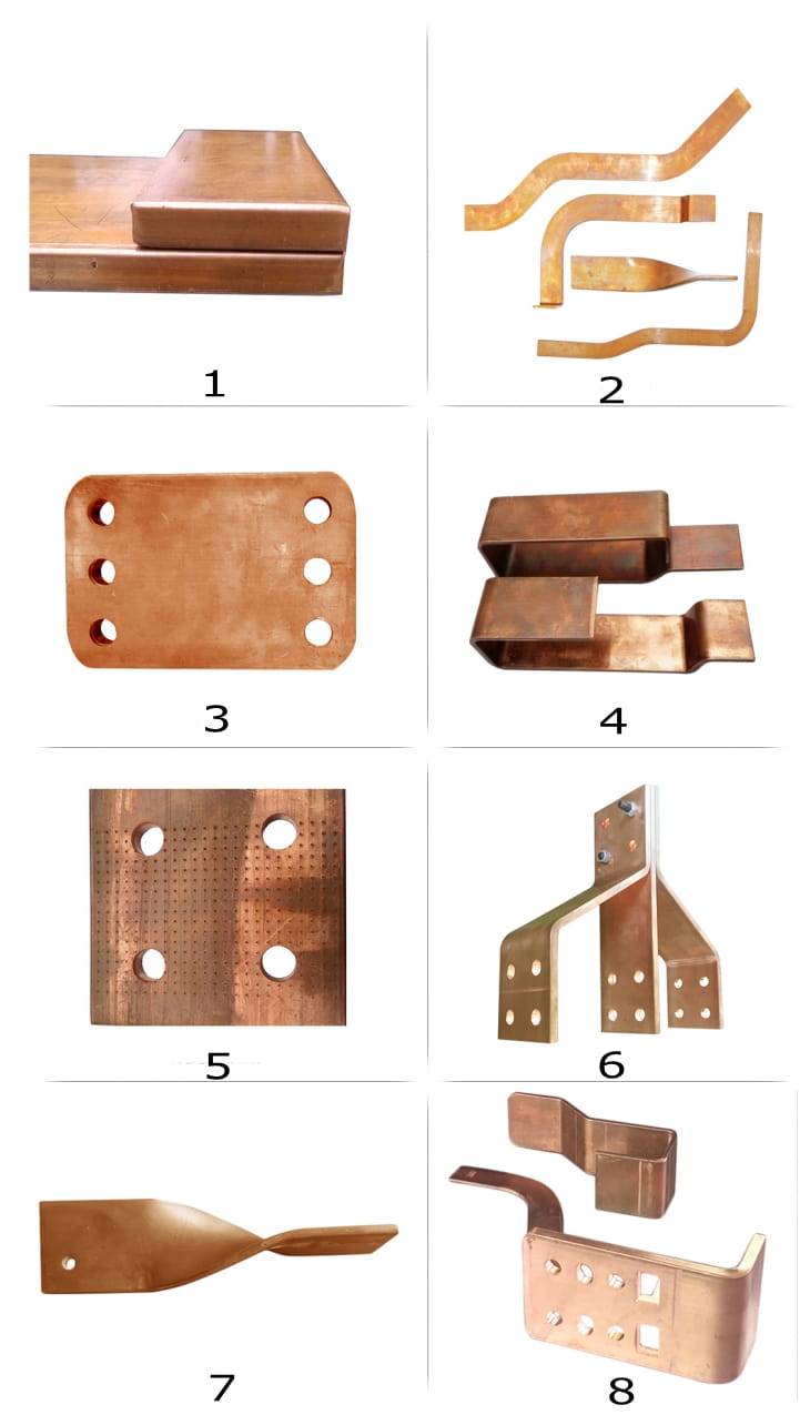
Bus bar various shapes and samples
1.Sheared bus bar plate 2.Standing bend and twisted bus bar 3.Holes punched bus bar 4.U shape bending bus bar 5.Holes punched and knurling pressed bus bar 6.8.Punch and bend combination bus bar 7.Twisted bus bar

